


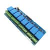


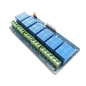
ADIY 8 CHANNEL 5V RELAY BOARD
Original price was: ₹600.00.₹281.00Current price is: ₹281.00. (Including GST)
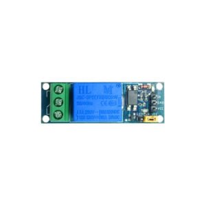
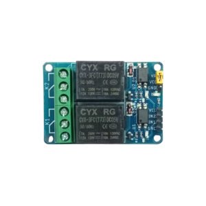
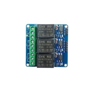
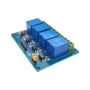
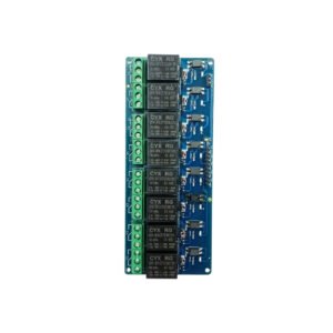
design, high-end SMT process. It has power and relay operation instructions. Relays terminals (C, NC, NO) are accessible through screw terminals which makes wiring up the board very easy. The inputs of the 8 Channel 5V Relay Module are isolated to protect any delicate control circuitry.
Application: 5V 8 Channel Relay Module
- To Control solenoids
- Motors
- Bulbs and bulbs
- Lamps
- Smart home control
Description
- A high-level trigger refers to the signal voltage between input and trigger, can be understood as a signal input with VCC cathode short-circuit triggered away;
- Low-level trigger refers to the signal voltage between the input terminal and Earth OV trigger, can be understood as the signal input terminal and the GND negative electrode short circuit triggered away 1-channel relay module connection.
Features: 5V 8 Channel Relay Module
- It can control both AC and DC appliances such as Solenoids, Motors, lights, fans, etc.
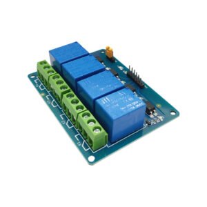
- High-quality screw terminals (Terminal Block) provided (C, NC, NO) for quick and easy
connection - Freewheeling diode to protect your microcontroller
- Input Signal Pin connected to Burg stick for easy accessibility
- LED Status indicators to indicate the relay ON/OFF status
- Mounting holes provided
- Signal input with a low-level signal, the common and often start conduction
- The relay can directly control all kinds of equipment and load
Specifications: 5V 8 Channel Relay Module
- Channel – 8
- Operating Voltage (VDC) – 5
- Trigger Voltage (VDC) – 5
- Switching Voltage (VAC) – 250@10A
- Switching Voltage (VDC) – 30@10A
- PCB hole diameter (mm) – 3.1
- Dimensions (Length* Width *Height ) – 140*57*18 m
Pin Description: 5V 8 Channel Relay Module
- C=common: This is the common terminal. This terminal will be connected to either of the other 2 terminals (NO or NC) based on the state of the relay.
- NO=normally open: As the name indicates this is a normally open terminal, i.e. if the relay is not energized (not ON), this pin will be open. We can say that the switch is OFF by default and when the relay is energized it will become ON.
- NC=normally close: As the name indicates it is normally closed terminal, i.e. if the relay is not energized (not ON), this pin will be closed. We can say that the switch is ON by default and when the relay is energized it will become OFF.
How to Work on 5V 8 Channel Relay Module
The eight-channel can be used to switch multiple loads at the same time since there are eight relays on the same module. This is useful in creating a central hub from where multiple remote loads can be powered, which is useful for tasks like home automation where the module can be placed in the main switchboard and can be connected to loads in other parts of the house and can be controlled from a central location using a microcontroller.
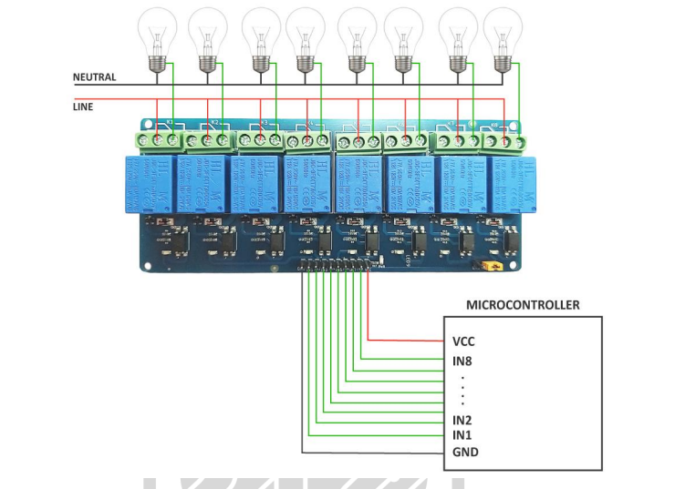
In this diagram, eight separate loads (represented by lightbulbs) have been connected to the NO terminals of the relay. The live wire has been connected to the common terminal of each relay. When the relays are activated, the load is connected to the live wire and is powered. This setup can be reversed by connecting the load to the NC terminal, which will keep it powered on till the
relay is activated.
Eight-Channel Relay Module Basic Troubleshooting:
If either of the relays does not turn on:
1. The contacts might be welded due to overcurrent/arcing. Shaking the module firmly might help unstick the contacts.
2. The driver circuitry might have been damaged due to overvoltage.
3. Input polarity might be incorrect.
4. Jumper might not have been moved to the correct position
Applications: 5V 8 Channel Relay Module
- To Control solenoids
- Motors
- Bulbs and bulbs
- Lamps
- Smart home control


Reviews
There are no reviews yet.