


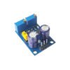


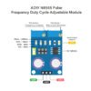
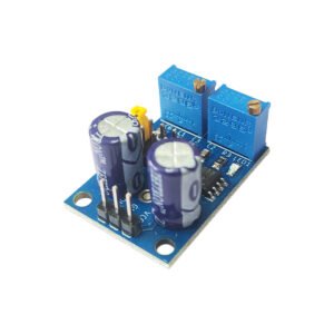
ADIY NE555 Pulse Frequency Duty Cycle Adjustable Module
Original price was: ₹100.00.₹61.00Current price is: ₹61.00. (Including GST)
NE555 Frequency Adjustable Pulse Generator Module – This module utilizes the NE555 IC and is designed to produce square wave pulses within the frequency range of approximately 4 Hz to 1.3 kHz. Perfect for experimental projects, stepper motor control, and an excellent resource for individuals looking to explore the functionalities of the LM555 IC.
Features: NE555 Pulse Frequency Duty Cycle Adjustable Module
- Main chip: NE555
- Input Voltage: 5V-15V DC.
- Generate an adjustable pulse for MCU.
- Generate an adjustable pulse, to control circuitry associated.
Description
The NE555 Pulse Frequency Duty Cycle Adjustable Module, is now available on our ADIY e-commerce platform! This versatile module is designed to generate precise 5V square wave signals, perfect for experimental development and driving stepper motors. With its adjustable pulse frequency and duty cycle, you have full control to fine-tune the output to meet your exact requirements. Whether you’re working on experimental projects or microcontroller applications, this NE555 module offers reliable performance and ease of use. Explore its capabilities today and unleash your creativity in electronics experimentation!
Get accurate, adjustable pulse frequencies with the NE555 Pulse Frequency Duty Cycle Adjustable Module. With its easy-to-use interface, you can fine-tune pulse frequency output to the exact rate you need. And, thanks to its adjustable duty cycle adjustments, you can select the perfect balance for your particular application. This NE555 square wave pulse generator module can be used to produce square wave signals for experimental development, in applications such as driving stepper motors, and as an adjustable pulse for microcontroller (MCU) applications.
Features: Ne555 pulse frequency duty cycle adjustable module
- Input Voltage: 5V-15VDC
- Output amplitude: 4.2V V-PP to 11.4V V-PP.
- Output Current : 15mA for 5V & 35mA for 12V.
- Size: 31mm * 22mm.
- Minimum – 50% duty cycle, 3.7 Hz & Maximum – 98% duty cycle, 1.3KHz
- Generate an adjustable pulse for MCU.
- Generate an adjustable pulse, to control circuitry associated.
- The output current can be 15 MA around; when 12V power supply, the output current can 35 MA around
- Output with LED indication(low level, LED will on; high level, LED will off; low frequency, the LED flashes).
- Max Output Current: >= ≥15MA (5V power supply, V-PP greater than 50%), >=35MA (12V power supply, V-PP greater than 50%)
The output frequency is adjustable:
- Period T = 0.7 (RA +2 RB) C
- RA, RB is 0-10K adjustable;
- Low profile when C = 0.001UF;
- IF stalls C = 0.1UF;
- High-frequency file C = 1UF;
- HF stalls C = 100UF;
- So buyers can calculate the frequency of the waveform.
Application: Ne555 pulse frequency duty cycle adjustable module
- As a square wave signal generator generates a square wave signal used for experimental development.
- Used to drive a stepper motor for generating a square wave drive signal.
- Generate an adjustable pulse for MCU.
- Generate an adjustable pulse, to control circuitry associated.
Ne555 pulse frequency duty cycle adjustable module Features & Operation:
- Size: 31mm * 22mm(1.2″ x 0.9″)
- Main chip: NE555
- Input Voltage (VCC): 5V-15VDC
- Input current:~100MA
- Output amplitude: 4.2V V-PP to 11.4V V-PP. (Varies with VCC voltage)
- Maximum output current: 15MA (VCC=5V, V-PP greater than 50%), 35MA (VCC=12V, V-PP greater than 50%).
- Output LED indicator (low level, LED is on, high level, LED is off; LED flashes with frequency. When the frequency is higher than about 30Hz, the LED will appear to be always on since the blinking is too fast to see.
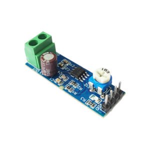
- There is a 4-row x 2-pin header that provides jumper settings to select different frequency ranges. The jumper connects different value capacitors in the circuit to change the RC time constant of the circuit. The multi-turn potentiometer near the frequency range jumper provides fine control over the frequency once the range is set.
- Jumper settings are:
~1Hz ~ 40Hz
~40Hz ~ 500Hz
~500Hz ~ 40kHz
40kHz ~ >200kHz - The jumper ranges will vary between modules depending on the tolerances of the components used.
- The output duty cycle can fine-tuned using the onboard potentiometers. The duty cycle and frequency are not separately adjustable; adjusting the duty cycle will change the frequency.
- The output frequency and duty cycle are adjusted using the following variables:
- Period T = 0.7 (RA +2 RB) C
- RA and RB are 0-10K Ohm adjustable potentiometers
1Hz ~ 50Hz: C = 0.001UF
50Hz ~ 1kHz: C = 0.1UF
1KHz ~ 10kHz: C = 1UF
10kHz ~ 200kHz: C = 100UF
Package includes:
1 x NE555 Pulse Frequency Duty Cycle Adjustable Module Square Wave Signal Generator


Reviews
There are no reviews yet.