

ADIY 4 CHANNEL 5V RELAY BOARD
₹300.00 Original price was: ₹300.00.₹142.00Current price is: ₹142.00. (Including GST)
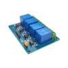
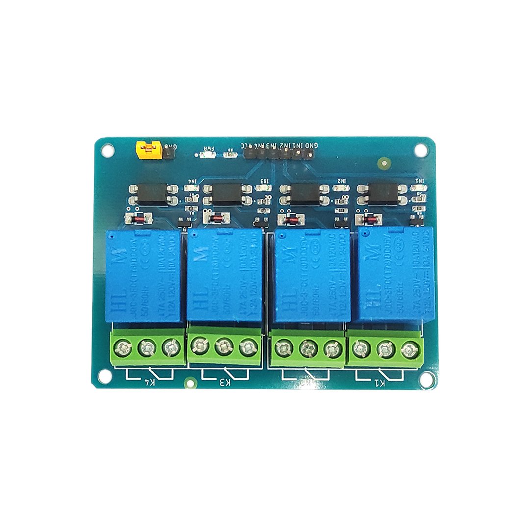
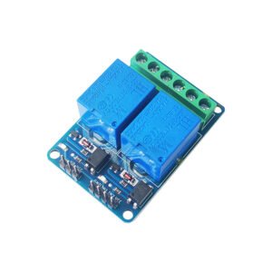
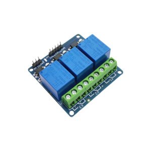
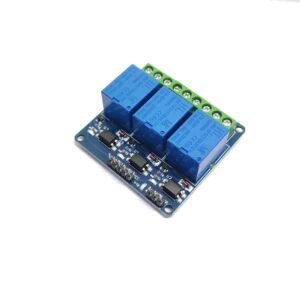
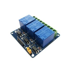
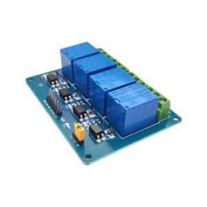
ADIY Relay Board 5V 4 Channel is a versatile 4-channel isolated relay module designed for easy control by various microcontrollers like Arduino, AVR, PIC, ARM, and more. With a maximum contact capacity of AC250V 10A and DC30V 10A, it can efficiently handle a variety of appliances and equipment with high current requirements.
This relay board features red working status indicator lights for safe operation and is suitable for a wide range of applications including MCU control, industrial automation, PLC control, and smart home systems. Each relay can be individually controlled for switching on/off via optoisolated digital inputs, which can be directly connected to microcontroller output pins. Notably, the board requires only approximately 1.0V to switch inputs on, but it can handle input voltages up to 5V, making it compatible with devices ranging from 1.0V to 5V, thereby offering flexibility in usage scenarios.
Application: 4-channel relay module
- To control high-voltage
- To control high current loads such as motor
- To control solenoid valves
- To control lamps and AC load
Description
4 Channel Relay Module 5V by ADIY
It is a 4 Channel Isolated 5V 10A Relay Module, A wide range of microcontrollers such as Arduino, AVR, PIC, ARM, and so on can control it. It is also able to control various appliances and other types of equipment with a large current. Relay output maximum contact is AC250V 10A and DC30V 10A. One can connect a microcontroller with a standard interface directly to it. Red working status indicator lights are conducive to safe use. It has a wide range of applications such as all MCU control, industrial sector, PLC control, and smart home control. Each relay can individually switch on/off by an opto-isolated digital input, which can connect directly to a microcontroller output pin. It only requires a voltage of approx 1.0V to switch the inputs on but can handle input voltages up to 5V. This makes it ideal for 1.0V to 5V devices.
Features:- 4 Channel Relay Board 5V
- One normally closed contact and one normally open contact
- Triode drive, increasing relay coil
- High-impedance controller pin
- Pull-down circuit for the avoidance of malfunction
- Power supply indicator and Control indicator lamp
- The power supply and relay instructions lit, and the disconnect is off
- The input signal, signal, common Terminal and start conducting
- Useful for appliance control
- DC or AC signal, control, you can control the 220V AC load
- There is a normally open and one normally closed contact
- The module is compliant with international safety standards, control, and load areas isolation trenches
Specifications :- Relay Board 5V 4 Channel
- No. of Channels: 4
- Trigger Voltage: 5V
- Trigger Current: 20mA
- Switching Voltage: 250VAC@10A
- Switching Voltage: 30VDC@10A
- Dimensions: Length*Width*Height = 73*52*13 mm
Pin Description – ADIY 4 Channel Relay 5V
- Input:
- VCC: Positive supply voltage
- GND: Ground
- IN1–IN4: Relay control port
- Output:
- Connect a load, DC 30V/10A,AC 250V/10A
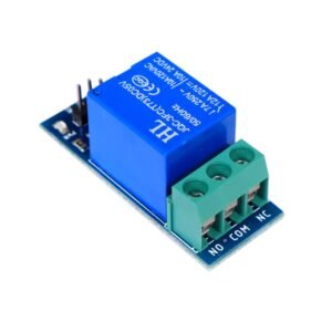
- C=common: This is the common terminal. This terminal will be connected to either of the other 2 terminals (NO or NC) based on the state of the relay.
- NO=normally open: As the name indicates this is a normally open terminal, ie. if the relay is not energized (not ON), this pin will be open. We can say that the switch is OFF by default and when the relay is energized it will become ON.
- NC=normally close: As the name indicates it is a normally closed terminal, ie. if the relay is not energized (not ON), this pin will be closed. We can say that the switch is ON by default and when the relay is energized it will become OFF.
How to Work With 4 Channel Relay Module 5V:
The four-channel can be used to switch multiple loads at the same time since there are four relays on the same module. This is useful in creating a central hub from where multiple remote loads can be powered. It is useful for tasks like home automation where the module can be placed in the main switchboard and can be connected to loads in other parts of the house and can be controlled from a central location using a microcontroller.
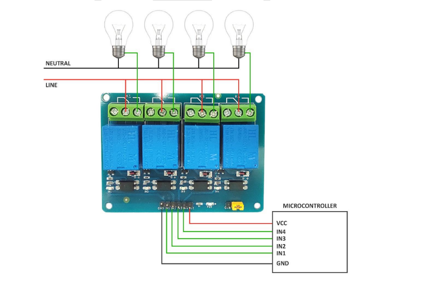 In this diagram, four separate loads (represented by lightbulbs) have been connected to the NO terminals of the relay. The live wire has been connected to the common terminal of each relay. When the relays are activated, the load is connected to the live wire and is powered. This setup can be reversed by connecting the load to the NC terminal that keeps it powered on till the relay is activated.
Application: Relay Module 5V 4 Channel
- To control high-voltage
- To control high current loads such as motor
- To control solenoid valves
- To control lamps and AC load









Reviews
There are no reviews yet.