

LDR Module – ADIY
₹70.00 Original price was: ₹70.00.₹27.00Current price is: ₹27.00. (Including GST)
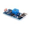
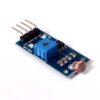
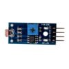
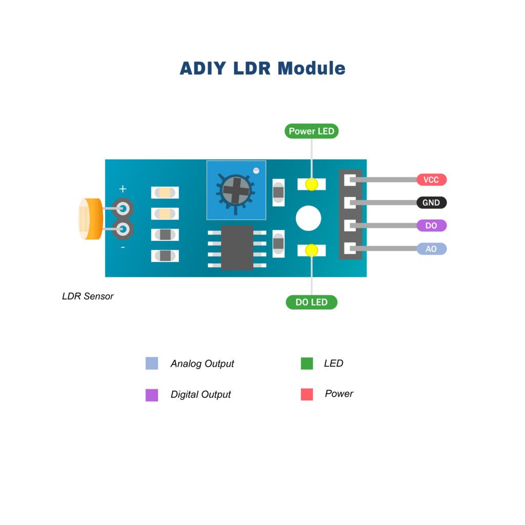
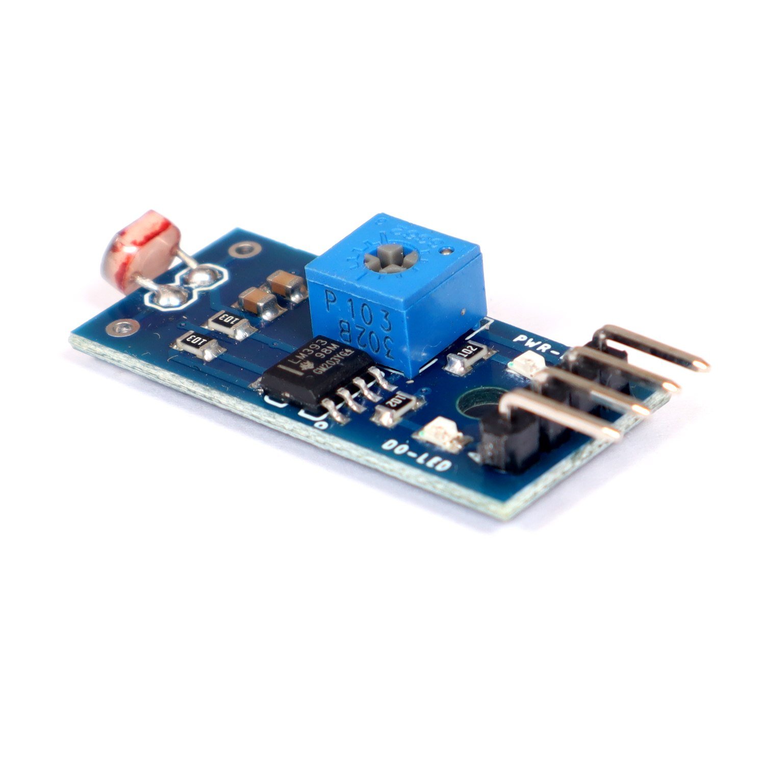
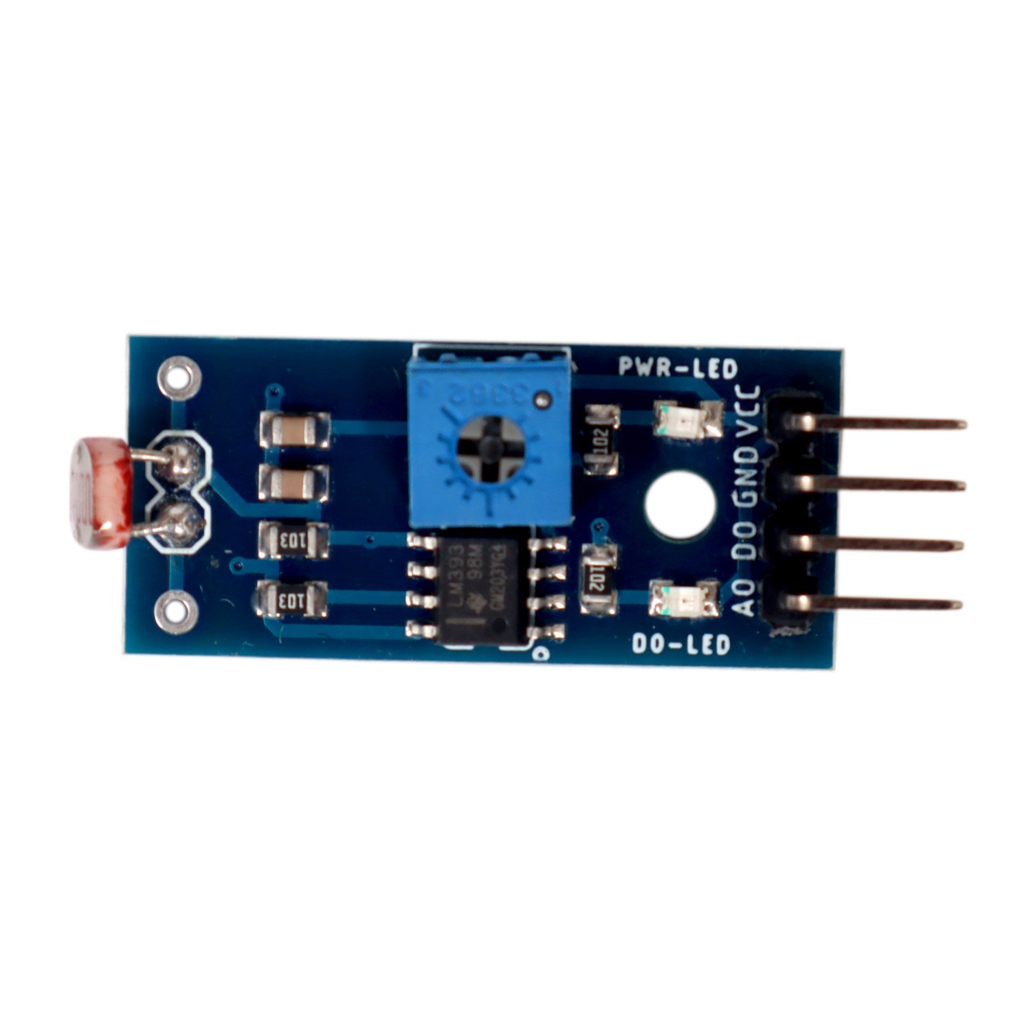
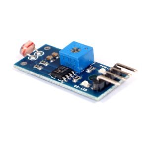
LDR Module – ADIY LDR sensor module is used to detect the intensity of light. It is associated with both the analog output pin and digital output pin labeled as AO and DO respectively on the `board. When there is light, the resistance of LDR will become low according to the intensity of light. The greater the intensity of light, the lower the resistance of LDR. The sensor has a potentiometer knob that can be adjusted to change the sensitivity of LDR towards light.
Features: Light Dependent Resistor Module
1. Can detect ambient brightness and light intensity
2. Adjustable sensitivity (via blue digital potentiometer adjustment)
3. Output Type: Analog and Digital
4. With fixed bolt hole for easy installation
Description
- LM393-based design.
- It can detect ambient brightness and light intensity.
- Adjustable sensitivity (via blue digital potentiometer adjustment).
- Output Digital – 0V to 5V, Adjustable trigger level from preset.
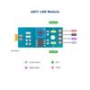
- LEDs indicating output and power.
- Mounting hole
- Power and Signal indicator LED
- Analog and Digital Out
- Adjustable threshold (via potentiometer)
- Input Voltage (V): 3.3 to 5
- Maximum power dissipation is 200mW
- The maximum voltage at 0 lux is 200V
- The peak wavelength is 600nm
- The minimum resistance at 10lux is 1.8kΩ
- Maximum resistance at 10lux is 4.5kΩ
- Typical resistance at100lux is 0.7kΩ
- Dark resistance after 1 sec is 0.03MΩ
- Dark resistance after 5 sec is 0.25MΩ
Advantages: LDR Module
- Sensitivity is High
- Simple & Small devices
- Easily used
- Inexpensive
- There is no union potential.
- The light-dark resistance ratio is high.
- Its connection is simple
Applications:LDR Module
- Light sensitive devices
- Light intensity meter
- Burglar alarm circuit
How LDR Module works:
the threshold voltage, so the sensor output goes LOW.
Package Includes – 1 x LDR Module.





Reviews
There are no reviews yet.