

ADIY IO Expansion module for Raspberry Pi Pico
₹350.00 Original price was: ₹350.00.₹182.00Current price is: ₹182.00. (Including GST)
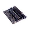
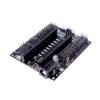
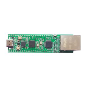
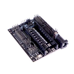
RP2040 Pico Expansion Board – Enhance Your Pico RP2040 Projects with the Pico RP2040 IO Expansion Shield
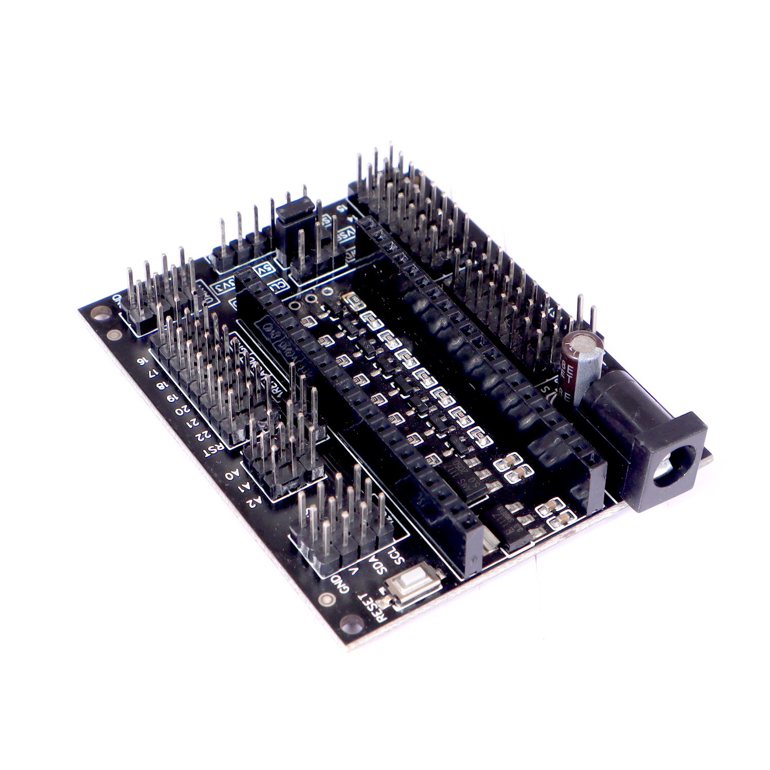
The RP2040 Pico Expansion Board by ADIY acts as a versatile breakout board for the Pico RP2040, simplifying the process of connecting various devices. Each pinout on the Pico RP2040 IO Expansion Shield includes power and GND pins, ensuring easy connection to sensors or servos. Additionally, some pinouts feature a 5V/3.3V selectable power option, making it seamless to work with both 5V and 3.3V digital devices.
This IO Expansion Shield is available either partially or fully assembled, allowing you to plug in your Pico RP2040 and start working immediately. Designed to facilitate easy connections, the Pico RP2040 IO Expansion Shield effectively expands the Pico RP2040 controller, enabling straightforward and hassle-free integration with multiple devices.
Enhance your projects and streamline your development process with the Pico RP2040 IO Expansion Shield.
Description
Features:- RP2040 Pico Expansion Board
- Power input via a barrel jack or VSYS header
- 23 GPIO are digital-only (GND, power, and signal format)
- 8 GPIO ports with 5V/3.3V selectable power
- 3 Analog pins with power output and GND
- 16 PWM pins
- 2 I2C ports with 3.3V power and 1 I2C port with a 5V/3.3V selectable power
- 1 UART port with 3.3V power and 1 UART port with a 5V/3.3V selectable power
- 1 SPI port with 5/3.3V selectable power
- 1 AREF output and 1 AGND output
- 1 SWD Port
- 1 3.3V, 1A capable regulator output, available all through the board
- 1 5V, 1A capable regulator output, available all through the board
- 1 Reset button
- 1 Power LED
Specifications: RP2040 Pico Expansion Board
- Input Voltage(V): 6 ~ 15
- No. of Analog Pins: 3
- No. of PWM Pin: 16
- Width (mm): 65
- Height (mm): 54
- Weight (gm): (need to measure)
- Shipment Weight: (need to measure)
- Shipment Dimensions : (need to measure)
Parameters:- RP2040 Pico Expansion Board
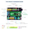
- DC Input: Supply input voltage to the board through this DC Jack. Input voltage can range between 7-12 Volts. This powers the onboard 5V and 3.3V, 1A regulators. The board can be powered either through this DC Jack or through the micro-USB connector on the Pico board. Both power supplies can be connected simultaneously without any problems.
- Power LED: Lights up when the board is powered either through the DC input jack or the Pico micro-USB connector.
- VSYS header: Another way to power the board. NOTE: “The simplest way to safely add a second power source to Pico is to feed it into VSYS via another Schottky diode.” Check section 4.5. “Powering Pico” in the Pico datasheet for more information.
- GPIO Block: Level Shiftable GPIO between 5V and 3.3V. 8 GPIO pins with POWER and GND pins next to each of the GPIO pins for ease of connection to various peripherals. This block of 8 GPIO pins can be level-shifted between 5V and 3.3V. Level Shifting is done using the VSEL jumper.
- GPIO Block: 3.3V GPIO only. 8 GPIO pins with POWER and GND pins next to each of the GPIO pins for ease of connection to various peripherals.
- SWD: Serial Wire Debug port for the Pico microcontroller.
- VSEL, Voltage Selector Switch. Switches the signal logic levels along with the corresponding VCC. Choose between 5V and 3.3V. Operates on GPIO Block 1(4), 2 I2C Ports (14), SPI Port (8), UART Port (9)
- SPI Port: Level Shiftable between 5V and 3.3V.
- UART Port: Level Shiftable between 5V and 3.3V.
- UART Port: 3.3V only
- GPIO Block: 3.3V GPIO only. 8 GPIO pins with POWER and GND pins next to each of the GPIO pins for ease of connection to various peripherals.
- AREF, AGND and GND Pins.
- Analog Block: 3 Analog pins with POWER and GND pins next to each of the analog pins for ease of connection to various sensors.
- I2C Ports: 2 I2C Ports with signal levels shiftable between 5V and 3.3V.
- I2C Port: Single I2C Port with 3.3V only signal level.
- Reset Switch: Resets the installed Pico microcontroller when pressed.
- Insert Pico here, with the micro-USB connector of the Pico ending up next to the DC Jack.
Shipment Dimensions :- RP2040 Pico Expansion Board

Package Includes – 1 x RP2040 Pico Expansion Board
Resources – Datasheet






Reviews
There are no reviews yet.